

Jay's Bottom End Buyers Guide - How to buy the right engine parts for your build
Introduction
For someone that doesn’t build race cars every day for a living, the process of selecting the right parts for an engine build within a given budget can sometimes be overwhelming. You spent some time saving up that money, spending it should be fun, not stressful.
Just winging it when selecting parts can get expensive. One poorly chosen part could lead to a total engine failure by unknowingly introducing a weak link in the chain that could have easily been avoided if you knew what questions to ask when picking out the parts. Skipping the planning phase is how people with good intentions accidentally end up with 900whp capable turbocharger, rods that will handle 1200 hp, and end up losing an engine because they had wrist pins that shouldn’t be pushed over 800whp.
This guide is going to explain the differences between the parts you are going to end up choosing from for your build. We will present you with the questions you should be asking, and the knowledge to answer them. By the time you finish reading this guide, it will hopefully have replaced your uncertainty and hesitation with knowledge and confidence.
This guide is broken up into chapters and chapter subsections. Below we will include an outline as a table of contents that allows you jump ahead to a specific section if necessary.
If at any point in this guide you have questions, or you feel like getting a second opinion, we are available and ready to help you perfect your plan before getting started. We are only a click away.
-
Goal Setting
-
The Anatomy of an engine
-
Material
GOALS DRIVE THE PROJECT TO SUCCESS (OR FAILURE)
Building a car is a lot less stressful when you have a plan that leads to a goal. Imagine trying to build a house without blueprints, a material list, a budget, or even a drawing of what the house should look like when it's done. That doesn't happen in the construction world because they know that the end result depends on the planning phase. Like houses, a poorly planned car build can end up costing a lot more money, taking a lot longer to complete, and turning out worse in the end.
Having a defined goal for the car makes the parts selection process much easier, because a lot of the options will drop out as you filter the attributes to the values that are most appropriate for your specific goal.
Let's start with 3 easy questions to answer:
-
What type of fuels do you plan on using? Strictly pump gasoline? Race Gas? E85? Or maybe a combination of pump gas during the week and race fuel at weekend track days.
The type of fuel the engine runs on will restrict what compression ratios you can run, how much boost and/or nitrous you can run, and ultimately the maximum amount of power you can make.
-
How much power do you want to make? (if you are having trouble picking a number, start with how fast you want to go in the 1/8mi, 1/4mi, or 1/2mi and work your way backwards to get a required horsepower number from that.)
Deciding on a maximum power level will simplify decisions like wrist pin thickness, rod beam style, and compression ratio. -
How will you be using the car? Daily driver? Weekend toy? Dedicated track car? Drag Racing? Drifting? Autocross? Road Racing?
Engines that road race have to put up with extended periods of heat while engines that drift or drag race typically have to put up with extended periods of high rpm. Knowing the type of “life” the engine will have to live through will help when deciding on rod bolts, rod length, stroke, and bearing clearance.
We will circle back to this goal setting section several times over the next few chapters, so spend some establishing a goal by answering the questions above. Here is an example of a realistic goal to get you started:
My goal is to have a car that I can drive to work on 93 octane pump gas Monday-Friday, but has the ability make 175hp per cylinder on E85 for weekend track days at the drag strip.
The Strength vs Weight vs Price Compromise
A topic that is going to come up in almost every chapter is the Strength vs Weight vs Price Compromise. This is a dilemma that manufacturers have to struggle with whenever releasing a product to market.
It is important to acknowledge that engines (like people) have a lifespan. Some component in the engine will eventually fail and need replacing to bring the engine back to life. The length of the engine’s lifespan depends on the parts inside the engine, and how they are treated over time. The engine that came in your car from the factory was specifically designed with a specific set of parts and ecu settings that the manufacturer believed could allow it to live for hundreds of thousands of miles or normal commuting. Every change we make to the engine in the quest for more power can change it’s lifespan. Most max effort race engines will not live as long as the engine in your everyday factory car on the road.
To make a product stronger, it often requires more material, which makes it heavier. If you look at a heavy duty max effort part next to a lightweight part, you will see the heavy duty part looks bulkier, stronger, and bigger. The problem with this is that heavier parts require more work from the engine to move them. Any time the engine has to work harder to move it's own parts, it will make less power and it’s lifespan will decrease by some amount.
The way to make a part stronger without increasing it's weight is to use a lighter material that is still strong enough to handle the abuse. The problem with these materials is that they often cost considerably more. This is where the Price component of the Strength vs Weight vs Price Compromise appears.
Ideally you would want all of your parts to be strong, lightweight, and cheap. However, as it turns out, you can usually only pick 2 of those 3.
Strong + Cheap = Heavy
Cheap + Lightweight = Weak
Strong + Lightweight = Expensive
So now imagine a manufacturer trying to bring a new engine component to the market.
Their first concern is that they want to minimize the risk of failures in the field. So they need to make the part strong.
As they start designing it for strength they realize they don't want to make it heavier than what the majority of the market needs, so they have to pick a power level to build it to, because that will dictate the weight. If they design it for too high of a power level, the majority of the people will have to over-build their engines to use the product, and make their engines work harder than they should have to. If they design it for too low of a power level, the majority of people will overpower and break it. So they try to design it in a way that will be strong just enough for the masses, without being too heavy.
Then they determine that by using higher end materials, they can make the product stronger without increasing it's weight. These more premium materials cost more money and end up driving the cost of the part up. If they make the part too expensive, the majority of people will not be able to afford it. But cutting cost by using inexpensive materials, could lead to a product with frequent failures.
So the manufacturer has to find a balance between building a part that is strong enough for a power level that most people will reach, without being any heavier than it needs to be, while staying within a budget that most people can afford.
Knowing this, the question then becomes if your goals are above or below the number that they chose to build the part to.

Pistons come in different sizes, and your engine won't go together correctly if you buy the wrong size. In this section we will discuss how to know what bore size is right for your project.
The “bore” is the hole (or “cylinder”) that the piston rides up and down in, inside the engine block. In order to have a healthy running engine, the piston has to fit “just right” inside the cylinder bore. Not too tight and not too loose. The pistons have expanding metal rings around them that end up pushing out against the inside edges of the cylinder bore, sealing the gap around the piston to make it airtight.
In a perfect world, the bore size selection process would be as simple as buying a standard sized piston for your standard sized block. However, as engines are run over time, the size, shape, and surface finish of the cylinder bore changes. Years of cyclic metal on metal contact can remove material from the cylinder bore turning what used to be a perfectly circular hole into an egg shaped hole with gouges or imperfections in the surface finish. When a cylinder bore changes size, shape, or surface finish, the seal between the piston and the cylinder wall becomes compromised. Imagine a circular peg in an oval hole. There would be some gaps where the oval’s ends get smaller. When these gaps form, compression leaks out of the combustion chamber while the engine is running. The engine makes less power, and consumes (burns) oil more quickly.
When building an engine, the block should always go to a machine shop for inspection first. If the machine shop determines that the size, shape, and/or surface finish of the cylinder bore is not good enough for a proper seal, they will recommend “boring it over”. Boring a block means spinning a cutting tool inside the cylinder, shaving material off of it's inner surface until what is left is a perfectly shaped circular hole with an ideal surface finish. But because material had to be cut away to make the hole circular and smooth again, that means the resulting hole is bigger than the original hole. A bigger hole needs a bigger piston. This is the first case that would call for a larger-than-standard (“oversized”) piston bore size.
Piston manufacturers make their pistons for the same engine in various diameters. They usually make a standard sized piston for engines that are still in good enough shape that they do not require boring, and they also make standardized over-size diameters that are usually larger than the standard size by 0.010” or 0.020” increments. (Ex: Std, +0.010”, +0.020”, +0.040”, etc). These stepped over-size bores are often referred to as “Service Sizes”. Machine shops know that these pistons come in these size options and they will bore the block to one of these sizes if they determine that a block requires boring. If a machine shop determines that the block will have to be bored 0.020” larger than standard size to make the hole perfectly shaped with an ideal surface finish, then you will end up buying pistons with a bore size that is 0.020” oversized.
At this point in the process (early) I see lots of people make the same mistake. In hopes of avoiding the down time and money spent on sending their block to a machine shop. They just cross their fingers and hope that the engine is still in good enough shape to run a standard sized piston without ever opening it up to check. In most cases, this ends up with a customer doing a piston exchange later, once they realize they actually need pistons that are larger than standard because their block needed machining. Or even worse, they end up with an engine that is low on power and constantly consumes oil.
I’ll take this opportunity to introduce the term “piston to wall clearance”. When you slide a piston into a cylinder, there is a tiny gap of air around the piston between the piston and the cylinder. When I say “tiny” I mean it could be less than the thickness of a human hair. This is what i was referring to earlier when I mentioned that the piston cannot fit too tight or too loose inside the cylinder bore. Too tight of a piston to wall clearance could cause the piston to seize inside the cylinder or cause accelerated material wear inside the engine, probably resulting in a total engine failure. Too loose of a piston to wall clearance could cause the piston to rattle around inside the cylinder allowing combustion and oil to leak past the piston rings, leading to a noisy engine that is low on power and consumes oil. Piston to wall clearance often plays a major role in whether an engine ends up performing well in race conditions or not.
Now that you know how important piston to wall clearance is in race applications, we can agree that it is a measurement you want to have control over SETTING to specific value, not a measurement you want to roll the dice and end up with randomly. Now let's revisit the topic of bore size with our new found piston to wall clearance knowledge. Lots of piston manufacturers make “standard size pistons” for your engine. If you took one piston from each manufacturer and measured them with the world’s most-accurate micrometers, you would see that if you read the measurement out to enough digits, they are all slightly different sizes. In the same respect, if you took 10 standard sized engine blocks and measured them the same way, you would notice that even they vary slightly in size between each other. Now imagine you grabbed any 1 of the standard sized pistons and dropped it into any 1 of the standard sized cylinders. You would end up with SOME piston to wall clearance. Grab another one of the standard sized piston and drop it into another one of the standard sized cylinders, you would end up with a slightly different piston to wall clearance. The question is, how different. The point of this exercise is to illustrate that you are rolling the dice when you attempt to use “standard sized” pistons in a “standard sized” cylinder. Maybe it's “right enough”, maybe it isn’t. The best way to have control over a measurement as important piston to wall clearance is to start with an oversized piston, and allow the machine shop to bore the cylinder to exactly the right size for THAT piston. They will build in the appropriate measurement to provide the correct amount of piston to wall clearance once assembled.
One question I get often at this point is from people that wonder “why not bore straight to the maximum limit that the block can handle, aren’t bigger engines better?” Yes, bigger engines are better. However to increase the engine’s displacement enough to provide a noticeable result purely by bore size alone, we are talking about a LARGE over bore. Much larger than just a couple service sizes. Typically this would require boring a cylinder further than what the factory block can handle, which would require aftermarket sleeves. We will cover that in an upcoming chapter so for now let's discuss the general pros and cons of boring over a lot vs boring over a little.
Simply put, the more material you remove, the weaker the block becomes. Most engines have enough material to allow room for 2 or 3 service sizes before requiring the block to have aftermarket sleeves installed. For example if your standard bore is 86mm, there are likely 86.25mm (+0.010” Over), 86.5mm (+0.020” Over), and 87mm (+0.040” Over) piston sizes available for your engine that can all be used without requiring the engine to be sleeved with aftermarket cylinder liners. That means stepping to the smallest service size up from standard would still leave you enough material in the block for 2 more rebuilds in the future where an overbore is required. Most factory engines start to encounter issues when you try to bore them more than 1.0mm (0.040”) over standard. One of the issues you can run into when trying to run too large of a bore in an engine is that the material between the cylinders becomes thinner as the bore gets larger. As the material becomes thinner and thinner between the cylinders, it becomes more prone to cracking, resulting in complete engine failure. Another issue that arises from having thin material between the cylinders is that the head gasket must also become very thin in that area with very little surface area from the block to seal against. So big bore engines often have trouble with blowing head gaskets, and require frequent servicing.
It is for this reason that we usually default to the next service size up from wherever the block measures before an engine build, while staying under the block’s maximum safe bore. Even if the cylinder is in great shape at standard bore, we will purchase a set of 0.010” or 0.020” oversized pistons to deliver with the block to the machine shop. We have them machine the block specifically to that set of pistons so we can ensure we end up with the optimal piston to wall clearance for that build. This method produces a more accurate and precise result than just asking the machine shop to blindly “bore it 0.020” over” without having the specific pistons in hand.
Piston > Bore Size > Summary Notes
-
Bore size is the diameter of the piston or cylinder in the block.
-
The size, shape, and surface finish of the cylinder change over time.
-
Piston to wall clearance is the measurement of the gap between the piston and the cylinder wall.
-
Piston to wall clearance is critical to a race engine’s performance. Problems arise if it is too tight or too loose.
-
Piston to wall clearance is measurement you want to set specifically, and should not be treated as a result that you randomly end up with.
-
It is rare for an engine being rebuilt with standard sized pistons to end up with an ideal piston to wall clearance for racing.
-
The way to control piston to wall clearance is to bore the cylinder a specific amount larger for a larger piston.
-
Boring a block too far can cause issues with cylinders cracking and head gaskets failing.
-
We recommend boring over the minimum amount required.
Pistons > Static Compression Ratio
Before we talk about what static compression ratio is, let's talk about why you should be interested in it, and how it can work against you. The static compression ratio directly affects the amount of power the engine makes. Generally speaking, If you had 2 properly setup identical engines with the only difference being that one of them has a higher compression ratio than the other, the engine with the higher compression ratio will make more power. However, as the compression ratio increases, so does the cylinder pressure. Increased cylinder pressure can cause the engine to be more prone to knocking (detonation) and at some point requires more careful tuning on higher quality fuels to avoid detonation related failures.
When the engine is running, the piston is moving up and down inside the cylinder. When the piston is at the bottom of it's rotation, the combustion chamber is at it's maximum volume. When the piston is at the top of it's rotation, the combustion chamber is at it's minimum volume. The compression ratio of an engine is the ratio of it’s combustion chamber’s maximum volume, to it's combustion chamber’s minimum volume.
The way to raise the compression ratio of an engine using only changes made to the piston is to change the shape of the top of the piston in such a way that it makes the volume of the combustion chamber smaller than usual when the piston is at the top of it's rotation. One way piston manufacturers do this is by building a dome shape onto the top of the piston to fill more of the void within the combustion chamber with piston material, leaving less room for air to exist. This dramatically reduces the “minimum combustion chamber volume”, therefore increasing the compression ratio as a result.
Alternately, the way to lower the compression ratio of an engine using only changes made to the piston is to remove material from the top of the piston in such a way that it INCREASES the volume of the combustion chamber when the piston is at the top of it's rotation. This portion of removed material often looks like a dish in the top of the piston. Increasing the combustion chamber volume at the top of the piston’s rotation lowers the compression ratio as a result.
Let's look at an example. Let's say one combustion chamber of a 2.0L 4cyl engine has a volume of 500cc when the piston is at the bottom of it's rotation. And a volume of 50cc when the piston is at the top of it's rotation. The compression ratio would be 500:50 or 10.0:1 after simplification. Now let's say you wanted to select a piston that could LOWER that compression ratio from 10.0:1 to 9.0:1 without changing the engine’s stroke (which we will talk about in an upcoming chapter). If you chose a piston that had enough material removed from it's top surface to allow for just 6cc more air in the combustion chamber (-6cc dish), the compression ratio calculation would change to 506:56 which is 9.0:1. Alternatively, if you wanted to raise the compression ratio from 10.0:1 to 11.0:1 you could choose a piston with enough material added to the top of it to reduce the combustion chamber volume by 5cc (+5cc dome). The compression ratio calculation would change to 495:45 which is 11.0:1. Now you know how the shape of the top of the piston (dish/dome) affects the compression ratio, and how the compression ratio affects the power output of the engine.
Forced Induction from turbochargers or superchargers also end up increasing cylinder pressure by pressurizing the air entering the engine. If we remember that increasing compression ratio also increases cylinder pressure, that means that increasing compression ratio with forced induction produces a combined effect on increasing cylinder pressure. It is for that reason that it is not common to see increased compression ratios with forced induction in race applications unless high end race fuels are carefully being used. Usually you will see one or the other; lower compression ratios with forced induction, or higher compression ratios without forced induction.
So how do you determine the right compression ratio for your build? Every engine is different. Below I have included a table with some general guidelines for popular engines we support.
-
If your engine came from the factory with forced induction, a safe place to start is stay close to your factory compression ratio. The higher you go from there, the better fuel will be required.
-
If your engine came from the factory naturally aspirated, and you intend on running forced induction, you may want to go with a compression ratio lower than stock.
-
If your engine came from the factory naturally aspirated and you intend on making more power while keeping it naturally aspirated, you will want to go with a compression ratio higher than stock.
|
TOYOTA |
Stock Compression |
Pump Gas + N/A |
Race Gas + N/A |
Pump Gas + Boost |
Race Gas / E85 + High Boost |
|
|
4A-GE |
9.5:1 |
9.5:1 - 10.5:1 |
10.5:1+ |
9.0:1 - 10.0:1 |
9.0:1 - 10.0:1 |
|
|
1JZ-GTE |
9.0:1 |
x | x |
8.5:1-9.2:1 |
9.0:1-10.0:1 |
|
|
2JZ-GTE |
8.6:1 |
x | x |
8.5:1 - 9.3:1 |
9.0:1 - 10.0:1 |
|
|
3S-GTE |
8.5:1 |
x | x |
8.5:1 - 9.0:1 |
9.0:1 + |
|
|
NISSAN |
Stock Compression |
Pump Gas + N/A |
Race Gas + N/A |
Pump Gas + Boost |
Race Gas / E85 + High Boost |
|
|
CA18DET |
8.5:1 |
x | x | 8.4:1 - 9.0:1 | 8.4:1 + | |
|
SR20DET |
8.5:1 |
x | x | 8.5:1 - 9.2:1 | 9.0:1 - 11.0:1 | |
|
RB20DET |
8.5:1 |
x | x | 8.5:1 - 8.6:1 | 8.5:1 + | |
|
RB25DET |
8.9:1 |
x | x | 8.0:1 - 9.0:1 | 9.0:1 - 10.2:1 | |
|
RB26DETT |
8.6:1 |
x | x | 8.0:1 - 9.0:1 | 9.0:1 - 10.2:1 | |
|
KA24DE |
9.5:1 |
9.5:1 - 10.5:1 | 10.5:1 - 11.5:1 | 8.7:1 - 9.1:1 | 9.0:1 - 10.5:1 | |
|
VG30DE(TT) |
8.6:1 |
8.6:1 - 10.5:1 | 10.5:1 - 11.0:1 | 8.4:1 - 9.0:1 | 9.0:1 - 10.5:1 | |
|
VQ35DE |
10.2:1 |
10.5:1 - 11.0:1 | 11.0:1 - 11.5:1 | 8.5:1 - 9.0:1 | 9.0:1 - 10.5:1 | |
|
VR38DETT |
9.0:1 |
x | x | 9.0:1 - 9.5:1 | 9.5:1 - 10.0:1 | |
|
SUBARU |
Stock Compression |
Pump Gas + N/A |
Race Gas + N/A |
Pump Gas + Boost |
Race Gas / E85 + High Boost |
|
|
FA20 |
12.5:1 |
12.5:1 - 13.5:1 | 12.5:1 - 13.5:1 | 9.0:1 - 9.5:1 | 9.5:1 - 10.6:1 | |
|
FA20DIT |
10.6:1 |
10.6:1 | 10.6:1 | 10.0:1 - 10.6:1 | 10.0:1 - 10.6:1 | |
|
EJ205 |
8.1:1 | x | x | 8.0:1 - 8.7:1 | 8.7:1 - 9.5:1 | |
|
EJ207 |
8.1:1 |
x | x | 8.0:1 - 8.7:1 | 8.7:1 - 9.5:1 | |
|
EJ255 |
8.4:1 | x | x | 8.2:1 - 9.2:1 | 9.0:1 - 10.9:1 | |
|
EJ257 |
8.2:1 | x | x | 8.0:1 - 9.2:1 | 9.0:1 - 10.1:1 | |
|
MITSUBISHI |
Stock Compression |
Pump Gas + N/A |
Race Gas + N/A |
Pump Gas + Boost |
Race Gas / E85 + High Boost |
|
|
4G63 |
8.5:1 |
x | x | 8.5:1 - 9.0:1 | 9.0:1 - 10.8:1 | |
|
4B11 |
9.0:1 |
x | x | 8.8:1 - 9.4:1 | 9.0:1 - 10.8:1 | |
|
HONDA |
Stock Compression |
Pump Gas + N/A |
Race Gas + N/A |
Pump Gas + Boost |
Race Gas /E85 + High Boost |
|
|
F20C |
11.0:1 |
11.0:1 - 11.6:1 | 11.6:1 - 12.5:1 | 8.4:1 - 9.1:1 | 9.0:1 - 10.3:1 | |
|
F22C |
11.1:1 |
11.3:1 - 11.9:1 | 11.3:1 - 13.5:1 | 9.0:1 - 9.7:1 | 9.5:1 - 10.7:1 | |
|
B16A2 |
10.2:1 |
10.2:1 - 11.9:1 | 11.0:1 - 12.4:1 | 8.8:1 - 10.0:1 | 10.0:1 - 11.0:1 | |
|
B18B1/2/3/4 |
9.2:1 |
9.2:1 - 11.9:1 | 12.0:1 - 13.2:1 | 8.8:1 - 10.0:1 | 10.0:1 - 11.0:1 | |
|
B18C1 |
10.0:1 | 10.0:1 - 11.9:1 | 12.0:1 - 14.0:1 | 8.7:1 - 10.0:1 | 10.0:1 - 11.0:1 | |
|
B18C5 |
10.6:1 | 10.6:1 - 11.9:1 | 12.0:1 - 13.6:1 | 8.8:1 - 10.0:1 | 10.0:1 - 11.0:1 | |
|
B20B/Z |
9.4:1 | 9.4:1 - 11.9:1 | 12.0:1 - 13.2:1 | 8.8:1 - 10.0:1 | 10.0:1 - 11.0:1 | |
|
K20A2 |
11.0:1 | 11.0:1 - 12.0:1 | 12.0:1 - 13.2:1 | 8.8:1 - 10.0:1 | 10.0:1 - 11.0:1 | |
|
K24A2 |
10.5:1 | 10.5:1 - 11.5:1 | 11.5:1 - 15.0:1 | 8.7:1 - 10.0:1 | 10.0:1 - 11.0:1 | |
|
H22A |
10.6:1 | 10.6:1 - 11.9:1 | 11.9:1 - 12.3:1 | 8.4:1 - 10.0:1 | 10.0:1 - 11.0:1 | |
|
MAZDA |
Stock Compression |
Pump Gas + N/A |
Race Gas + N/A |
Pump Gas + Boost |
Race Gas / E85 + High Boost |
|
|
B6 1.6L |
9.4:1 |
x | x | 8.5:1 - 8.7:1 | 8.7:1 + | |
|
BP 1.8L |
9.4:1 |
9.9:1 - 10.0:1 | 9.9:1 - 10.0:1 | 8.5:1 - 9.0:1 | 9.0:1 - 10.0:1 |
Piston > Compression Ratio > Summary Notes
-
Compression Ratio directly affects the power output of the engine.
-
Higher compression ratio makes more power than lower compression ratio.
-
Higher compression ratios require higher quality fuels to avoid detonation.
Pistons > Material
In the performance aftermarket, most pistons are either made from an aluminum alloy called “2618” or a less popular aluminum alloy called “4032”. One of the differences between these two alloys is that 4032 is harder than 2618. But when it comes to pistons, harder materials like 4032 are more prone to cracking during abuse than a softer alloy like 2618. Most piston manufacturers use 2618 alloy because of how well it survives in high abuse situations. Because it is softer than 4032, you can consider it as bending before it cracks. So why do some manufacturers still use 4032 alloy to make pistons out of?
This is a great time to introduce the concept thermal expansion. As the engine runs, the pistons absorb heat and they expand. If you remember back to the first section in this chapter we mentioned that the piston to wall clearance has to be “just right”, not “too tight” and not “too loose”. This means that the machine shop has to machine a little extra piston to wall clearance into the cylinder to account for the amount the piston will “grow” once it's at operating temperature. If they set the piston to wall clearance while the parts were at room temperature, the clearance would end up being too tight once it gets hot. This means that the piston to wall clearance is technically a little too loose until the pistons expand as they heat up to operating temperature.
As it turns out, 4032 expands less with heat than 2618 does. Less thermal expansion means you can run a tighter piston to wall clearance, because you don't have to machine the extra room in. So even though 4032 is more prone to cracking from abuse in high power applications, it does allow you to make a quieter running, tighter sealing engine that consumes less oil with a smaller piston to wall clearance. It is for this reason why we typically see 4032 pistons used in low to moderate power engine rebuilds that are expected to last hundreds of thousands of miles of daily driving.
So in general, 4032 pistons are more appropriate for low to moderate power rebuilds where a tighter seal is more important than handling high abuse, and 2618 pistons are appropriate for moderate to high power race applications
But not every engine can run a 2618 piston the way they come from the factory. For example, Honda H22A, F20C, and F22C engines all come from the factory with cylinder walls lined with Fiber Reinforced Metal. This particular metal does not react well with 2618 alloy, and cannot be bored and honed the same way as a typical cylinder wall. There is however a manufacturer that offers a coated 4032 piston that works in these engines without negative reaction of metals. It is common practice for those wanting to run 2618 pistons in high horsepower builds of engines that came with FRM cylinder walls to get their blocks re-sleeved with aftermarket sleeves that do not react negatively with 2618 pistons.
Piston > Material > Summary Notes
-
4032 alloy is harder than 2618. It expands less as it gets hot making it ideal for a tight sealing engine, but it is more prone to cracking under abuse in high power applications.
-
2618 is softer than 4032 so it can take more abuse before cracking, but expands more as it heats up so it requires a looser piston to wall clearance machining.
Pistons > Forging/Skirt Style
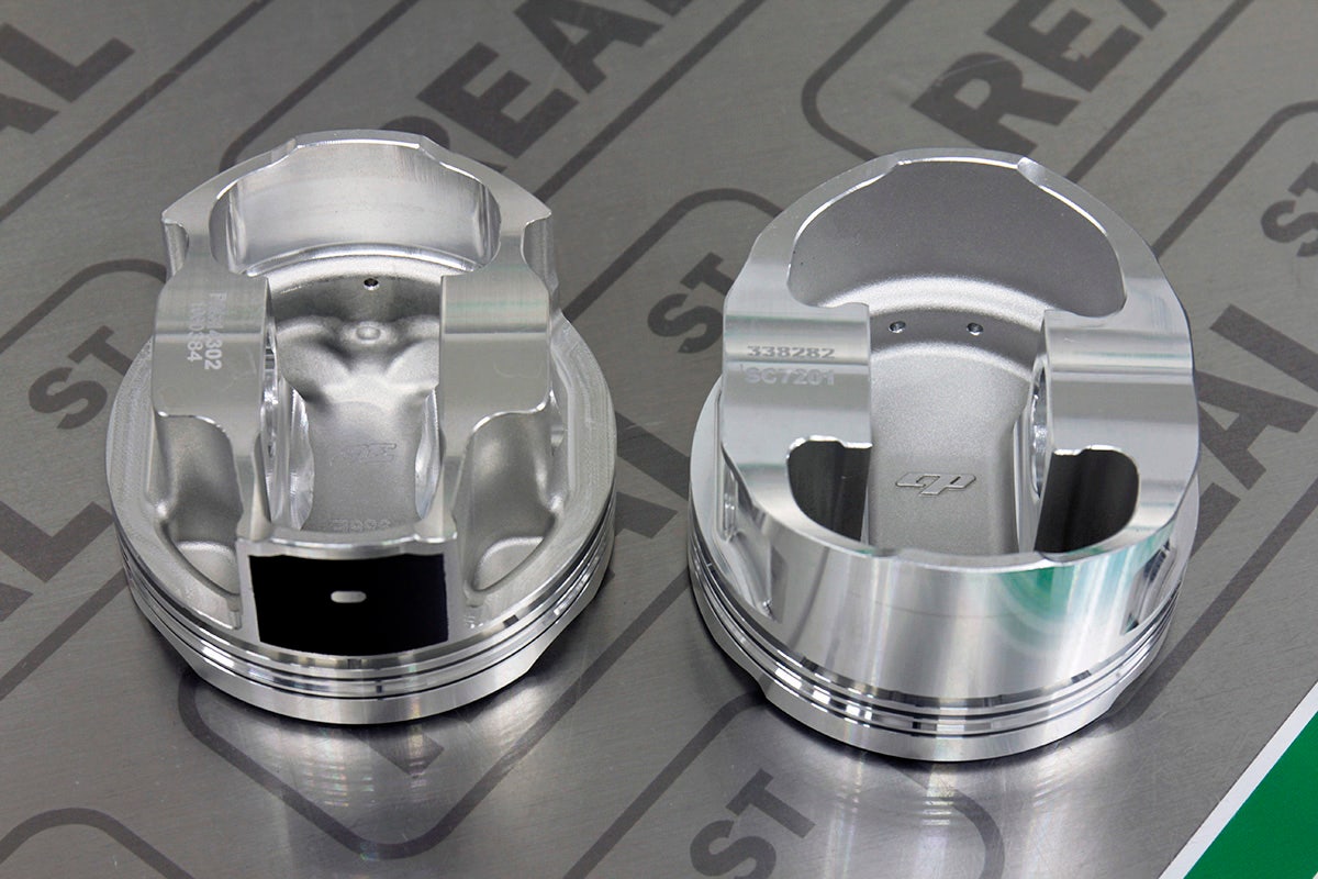
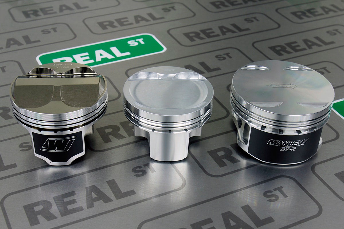
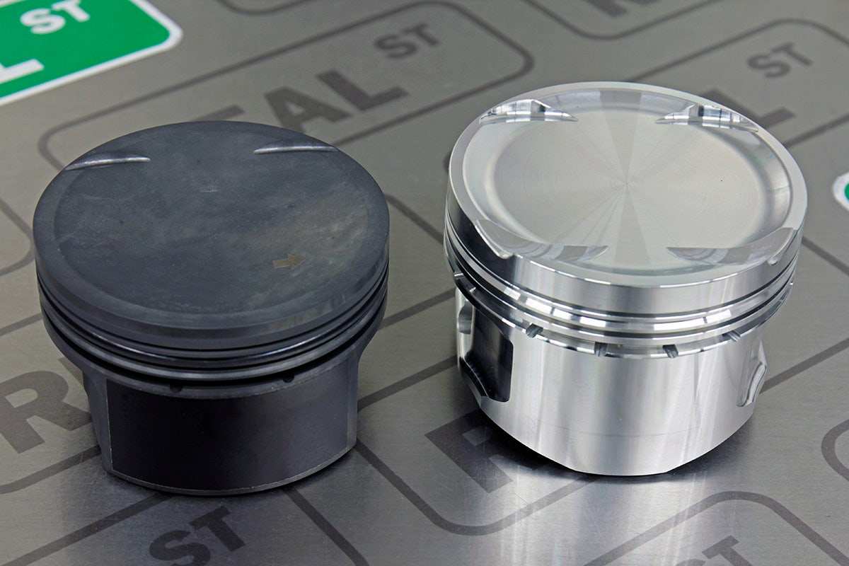
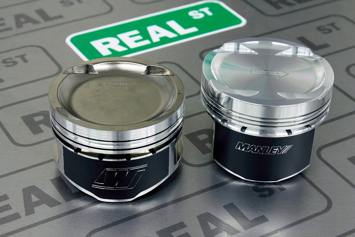
If you took one of each piston that each manufacturer makes for your engine and looked at them from the top, they would all look relatively similar. Some may have dishes and some may have domes, but you see the real difference when you flip them over and look at the bottom. There are a variety of different forging styles. Some are designed with maximum strength in mind and have more material in places where pistons typically fail from being overpowered. Others are designed with minimum weight in mind, and have the most material removed possible to produce the lightest part they can. This is the first case we are going to encounter of the Strength vs Weight vs Price Compromise mentioned at the beginning of this guide.
You will see some pistons have a “full-round” design that is very cylindrical and has very little material removed from the circular shape of the forging. These pistons usually have more material and can sometimes weigh more.
Some manufacturers have moved away from the full-round design, and started removing material from places on the piston that they feel do not compromise it's structural integrity to make it lighter. These pistons are the ones where it looks like the sides of the circle are missing when you look at them from the bottom.
All of these piston forging designs work. The question is, how strong of a piston do you need for your power goals. As a starting point, avoid lightweight pistons for higher horsepower builds, and avoid heavier pistons for lower power builds.
Piston > Forging/Skirt Style > Summary Notes
-
Pistons designed for naturally aspirated applications typically use forgings that have lots of material removed to make them lighter, which makes them too weak for high power applications
-
Pistons designed for high power applications typically use more material and weigh more than the lightweight pistons.
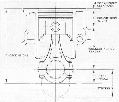
Pistons > Rod Length + Stroke + Compression Height = Deck Height
This section is going to be about the relationship between the pistons, the connecting rods, and the crankshaft. We are jumping ahead a little, but we will be coming back to this in future chapters.
Before we start diving into some calculations, first let's go over some theory.
The reason we are talking about rods and crankshafts in a piston section is because your piston options will change dramatically if your rod length or stroke changes from standard. So first let's talk about why someone would want to change the rod length or stroke of the engine.
The most common reason someone would want to change the stroke of an engine is to make the engine bigger or smaller. Most pistons available for your engine are designed to be used with a standard length rod, and a standard stroke crank. This produces a near-standard dimension engine that ends up being about the same displacement as it was from the factory. However, if you wanted to significantly change the displacement of your engine (make it noticeably bigger) you would need to replace your standard stroke crankshaft with one that has a larger stroke.
Now let's get into some measurement definitions and math.
The “Deck Height” of an engine is the measurement from the centerline of the crankshaft to the top deck of the cylinder block.
The “Stroke” of the crankshaft is the diameter of the circle drawn by the rotation of the center point of the rod journal as it spins.
The “Rod Length” is the distance from the center of the big end of the connecting rod to the center of the small end of the connecting rod.
The “Compression Height” of the piston is the distance from the centerline of the wrist pin, to the top of the piston.
Now let's look at how these 4 things work together. Half of the stroke of the crank, plus the rod length, plus the piston compression height must add up to no more than the deck height of the block or else the piston will collide with the cylinder head, and the engine will not run.
(Half of the Stroke) + (Rod Length) + (Piston Compression Height) <= Deck Height
Let's look at a real world example to put some numbers into this equation. We will use a 2.0L 4G63 engine from a Mitsubishi Evo 9.
Stroke = 88mm
Half Stroke = 44mm
Rod Length = 150mm
Piston Compression Height = 34.7mm
So that means
Deck Height >= (Half of the Stroke) + (Rod Length) + (Piston Compression Height)
Deck Height >= (44mm)+(150mm)+(34.7mm)
Deck Height >= 228.7mm
The actual deck height of the 4g63 engine is 228.8mm, which is slightly larger than 228.7mm. So this engine combination works.
Now let's say you wanted to increase the displacement of your 4g63 to be larger than 2.0L. We learned earlier that you can do this by using a crankshaft with a larger stroke. There are 100mm stroke crankshafts available for that engine. But let's see what would happen if all you did was change the stroke of the crankshaft without changing the rod length or compression height.
Stroke = 100mm
Half Stroke = 50mm
Rod Length = 150mm
Piston Compression Height = 34.7mm
Deck Height >= (Half of the Stroke) + (Rod Length) + (Piston Compression Height)
Deck Height >= (50mm)+(150mm)+(34.7mm)
Deck Height >= 234.7mm
This will not work, because the deck height of the 4g63 engine is 228.8mm. So, now we know that if we increase the stroke of the crankshaft, then 1 of the other measurements needs to get smaller to make up for it. If you increase stroke, either rod length or compression height will need to be smaller by the same amount.
In the particular case of the 4g63, they make up for the increased stroke with the use of a “stroker piston” that has a shorter compression height. Let's look at an example of a 4g63 stroker dimension that works successfully
Stroke = 100mm
Half Stroke = 50mm
Rod Length = 150mm
Compression Height = 28.7mm
Deck Height >= (Half of the Stroke) + (Rod Length) + (Piston Compression Height)
Deck Height >= (50mm)+(150mm)+(28.7mm)
Deck Height >= 228.7mm
It’s ok if you got lost in the numbers here. The engine parts manufacturers have already done the math for you. The important thing to remember here is that whenever you decide to deviate from the factory dimensions, you have to be very careful to select a piston, rod, and crankshaft that will physically fit together inside the engine. A stroker crank requires a stroker piston/rod combo.
Piston > Rod Length, Stroke, & Compression Ratio > Summary Notes
-
To noticeably change the displacement of the engine, you will need to replace the standard stroke crank with a stroker crank.
-
Changing the stroke of the engine will require the rod length and/or piston compression height to change as well.
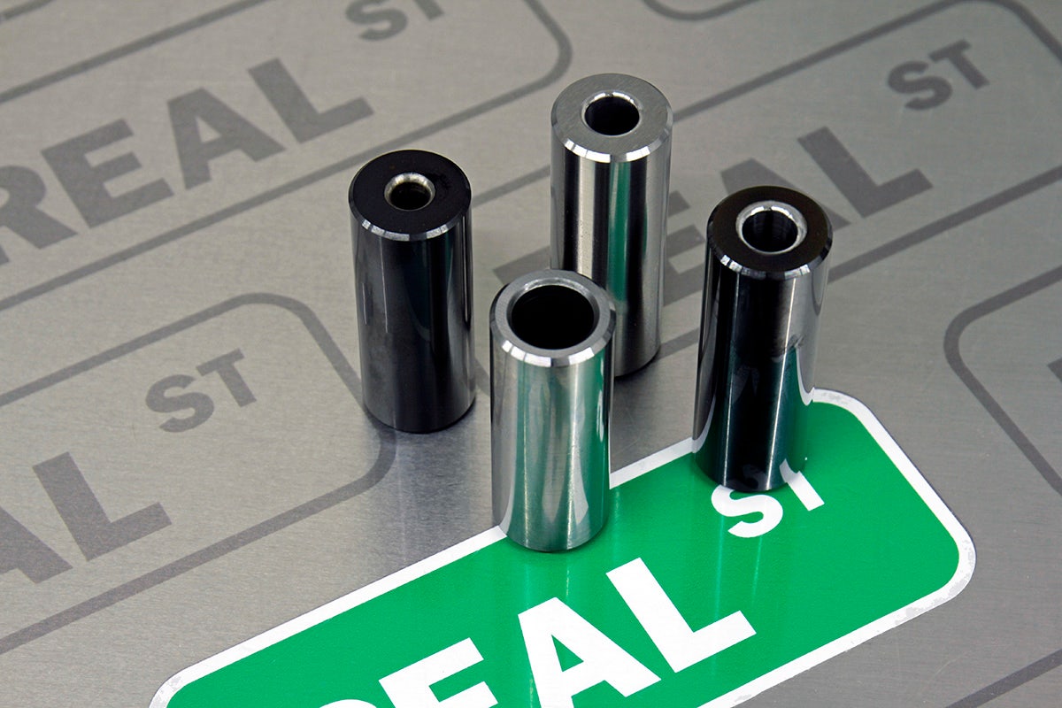
Pistons > Wrist Pins
The wrist pin is a steel tube that holds the piston to the connecting rod. Stronger wrist pins usually either have a thicker wall than lighter duty wrist pins, or they are made from a higher quality steel. When you buy a set of pistons, they will come with some set of wrist pins. Each manufacturer decides what kind of pin they are going to include in their kit. This is the second instance where we will encounter the Strength vs Weight vs Price Compromise.
There are thin-wall wrist pins that are lightweight, and adequate for factory rebuilds, or performance applications with moderate power goals. These usually have a wall thickness under 0.150”. These are usually included in aftermarket piston kits for free, at no additional cost.
There are thick-wall wrist pins that weigh considerably more. These are designed to handle the additional abuse of high power max effort engines. These are often an additional cost on top of a set of pistons.
And for those that are looking for max effort high power lightweight pins, there are options for higher quality materials at a premium price.
This is where we see many people make mistakes like the one we mentioned at the beginning of this guide. We see people run a 800hp capable turbocharger on an engine that was built with 900hp capable rods and they are still on the 600hp capable wrist pins that came in their piston kit because they didn't know any better. Some of them end up blaming the piston manufacturer when the engine dies, but it was really just the wrong combination of components for their specific goal.
Piston > Wrist Pins > Summary Notes
-
The wrist pins hold the pistons to the connecting rods.
-
The wrist pins that come with your pistons are a moderate compromise between strength and weight, and they may not be right for your build.
-
You can purchase lighter or stronger pins separately if a moderate pin is not ideal for your goals.
Pistons > Coatings
You will see multiple types of coatings when you start to look more closely at pistons. There are thermal barrier coatings, anti-corrosion anodizing, and anti-friction coatings.
The most common coating you see is the screen printed black anti friction coating on the skirts or sides of some pistons. This coating is added to the portion of the piston that comes in contact with the cylinder wall to reduce the amount of metal on metal friction.
Some piston manufacturers anodize parts of the piston to make them more resistant to wear and corrosion.
Some piston manufacturers offer optional thermal barrier coating on the skirts and/or crown of the piston. These coatings act as a barrier to keep heat from absorbing into the pistons. One thing to consider when preventing heat from going into the piston is, where will the heat then go instead? If you are going to use a thermal barrier coating on the piston, it is a good idea to have the combustion chamber area of the head coated as well so you don't end up redirecting additional heat into the head instead of the piston.
The coatings are not critical to the piston’s performance. Uncoated pistons work very well in race engines as do coated pistons. But it is still good to know why the coatings are there and what benefits they may offer.
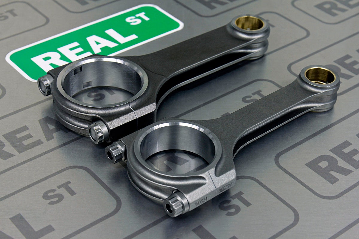
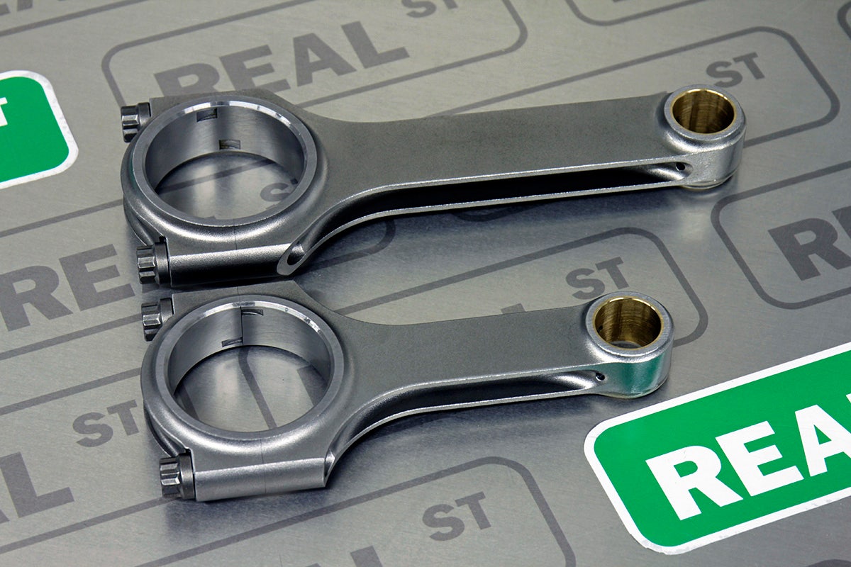
Connecting Rods > Beam Profile vs Weight
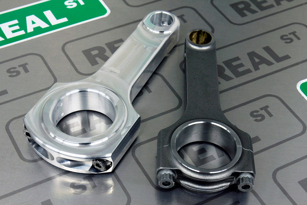
Many people get caught up in trying to decide if they should buy H-Beams or I-Beams. The truth of the matter is that the beam profile alone is not enough information to base a connecting rod selection off of. There are lightweight and heavy duty versions of both, and there are even more beam profile options than that for many engines. Before we talk about beam profile, first we should talk about the weight of the rod, and how much material is used in the places that matter.
Earlier we talked about the Strength vs Weight vs Price Compromise, we acknowledged that parts designed to handle high horsepower are often heavier than parts that are designed to live in lower effort applications. To make the parts stronger, they leave more material in the weakest places on the part which makes it heavier. And in lightweight naturally aspirated parts that don't need to survive in high power applications, material is removed to make the parts weigh less. Steel rods are, for the most part, the same way. A rod designed to handle high power typically weighs more because the rod is made of more material to make it stronger.
So let's look at two different H-Beams. One is a lightweight inexpensive H-Beam that is designed for stock to moderate effort engine rebuilds that will end up making around 75-100hp per cylinder. The other is a heavy duty H-beam that we have used in engines that run at over 200hp per cylinder. With this wide of a span in power capacity, it should be clear to see that beam profile alone is not enough information to base rod selection off of.
It may be easier for some of you than others depending on what engine you have. Maybe there are only 2 aftermarket rods available for your engine: a lightweight H-Beam, and a max effort I-Beam. If that is the case then the decision becomes very simple. But some of the engines we cater to have 20-30 connecting rod options to choose from. And it's important for us to learn to look more closely at the rod than beam profile alone.
Let's take a look at some important areas of the connecting rod that might help you visually recognize a heavy duty rod from a lightweight rod.
The Beam Profile refers to the shape of the cross-section of the middle of the connecting rod. If you cut an H-Beam in half and look at the cross-section, it looks like an H. There are also I-Beams, A-Beams, and X-Beams. Different manufacturers prefer different beam profiles.
If the strongest rod on the market for your engine happens to be an I-Beam, it isn’t BECAUSE it’s an I-Beam. It’s the strongest because it was designed with enough material in the right places to live in max effort applications. It may just so happen that none of the manufacturers have made a max effort H-Beam for your application yet. But when it comes to some applications like the Toyota 2JZ-GTE, there are multiple excellent max effort rods in a variety of different beam profiles.
When it’s time to select a connecting rod, first determine if you are going to be best off with a light weight rod, or a heavy duty rod. (I told you the goal setting portion in the first chapter was going to come up a lot). If you intend to make 150+hp per cylinder at some point with this engine, you should consider a heavier duty rod than if you are planning on staying under 100hp per cylinder. At this point many people ask “well should I just over-build the engine now while it's apart in case my goals increase over time?” If you want to build an engine once and you intend on making more power later, build the engine to the power level you think it will end up at. But over-building your engine for no reason is not always the best idea. Let's discuss the pro’s and cons of using heavy duty engine internals.
The benefit of using heavy duty engine internals that they can handle a lot of power without breaking. Well, that was easy.
Explaining the negative effects of heavy duty engine internals is a little more complicated. The heavier the rotating parts of an engine are, the harder the engine has to work to move them. Every time the crank turns, the pistons go up and down. While this is happening, the rotating parts are either being pushed together, or pulled apart. As the RPM increases, and you spin the parts faster and faster inside the engine, the weight becomes more and more important. Imagine doing 30 pushups in 1 minute (30rpm). Then imagine trying the same thing with an additional 100lbs of weight on your back. It would be much harder maintain the same 30 pushups per minute when your body weighs more. So if your engine’s maximum rpm is 8000rpm, the engine will be working harder at 8000rpm with heavier parts than it would with lighter parts.
But what happens to an engine when it works harder than it should to spin parts that are heavier than they need to be? Firstly, the engine itself will make less power than it would with lighter parts. Secondly, it could wear parts like bearings out past the end of their service life more quickly. And lastly, it could cause a fatigue failure like a broken rod bolt. (both of which we will learn about in upcoming chapters.)
So the challenging part of selecting a connecting rod is finding one that is heavy-duty enough to handle your power goals, but not any heavier than it needs to be.
Connecting Rods > Material
In the last section, we acknowledged that connecting rods with more material in key places are more likely to survive in higher power applications, and that this usually makes them heavier. We also acknowledged that heavier parts make the engine work harder which can lead to their own types of engine failures.
So if horsepower kills lightweight parts, and you need heavier parts with more material to handle the power, but the heavier parts make the engine work harder and shorten it's lifespan, then what is a hardcore racer supposed to do when they want to build a max effort engine that can survive an entire season or more?
The solution to this problem is to use a lighter material that will allow you to physically use more of it without adding up to an unreasonable amount of weight. Some manufacturers focus on the design and production of max effort aluminum connecting rods that can handle power levels over 200hp per cylinder while weighing less than the steel alternatives.
When you look at an aluminum connecting rod next to a steel one, you can immediately see how BIG the aluminum connecting rod looks. There is a lot of material in the places that matter. Because the aluminum is lighter, you can use a lot more of it to reinforce the critical areas of the rod.
But aluminum rods help in ways other than just weight. Remember when we acknowledged that the rotating assembly (pistons, connecting rods, crankshaft) are constantly in a state of being pushed together or pulled apart? Well sandwiched between the connecting rod and the crankshaft you will find rod bearings. As the parts push together and pull apart, the bearings get squeezed between the connecting rods and the crankshaft. The heavier the pistons and rods, the more the bearings get squeezed. If they get squeezed too much they can fail and kill the engine.
Because aluminum is softer than steel, you can think of an aluminum connecting rod acting more like a spring than a steel rod does. Imagine a steel rod transmitting 100% of the combustion force into squeezing the bearing. But because the aluminum rod is softer than the steel connecting rod, it can absorb some of that shock, transmitting less of it into squeezing the bearing.
So after hearing all of these great things about aluminum connecting rods, you may be wondering “why doesn’t everyone run aluminum connecting rods in their engines?” There are a couple things steel rods are better at. Remember when we talked about aluminum alloys in the piston chapter and we acknowledged that softer aluminum alloys survive abuse in race applications better than harder aluminum alloys that are more prone to cracking, but that softer aluminum expands more as it gets hotter. And that this needs to be taken into account when setting piston to wall clearance? Well aluminum rods get larger as they get hotter as well. This means oil clearance could increase at the rod bearing level with temperature as well and needs to be taken into account when setting bearing clearance. Also because aluminum is softer, it is more likely to permanently change shape over time where a steel rod wouldn't.
So here are some bullet point guidelines to summarize the differences in connecting rod materials.
Steel Connecting Rods
-
Pros
-
can last hundreds of thousands of miles.
-
can be made very strong.
-
can be made relatively inexpensive in large batches.
-
Cons
-
can become heavy in max effort applications, causing the engine to work harder.
-
transmit the full combustion force into the bearings.
Aluminum Connecting Rods
-
Pros
-
can be made in a max effort configuration with a lighter weight than steel.
-
can act as a shock absorber for the bearing, extending bearing life.
-
Cons
-
can be more expensive than steel rods because of small batch production costs.
-
can permanently change shape and require replacing sooner than a steel rod would.
Connecting Rods > Rod Bolts
In previous sections, we discussed how the pistons, connecting rods, and crankshaft are all pushed together and pulled apart repeatedly as the engine turns. The faster the engine spins (higher rpm), the more times the parts switch between being pushed and pulled per second. The more times they have to change direction per second, the harder it is to keep them together.
We’ve already learned that the wrist pin is what holds the piston to the connecting rod. The rod bolts are what hold the connecting rod to the crankshaft. The rod splits in half, and the two halves form a circle around the crankshaft. The rod bolts hold the two halves together.
That means when the parts switch from being pushed to being pulled, the full force of the pull is loaded into the rod bolt.
So as RPM increases, the rod bolt’s job gets harder and harder.
It is for this reason that engine builders will typically use an upgraded rod bolt (higher quality, more expensive material) in engines that will be operating at high rpm. Rod manufacturers include a standard rod bolt (usually ARP 8740 or ARP 2000 material) in their base connecting rods, but all of them offer an upgraded bolt for an additional cost. Sometimes you are building an engine that you intend to use at high rpm, but sometimes race engines will experience unexpected encounters with high rpm like during a misshift. The rod bolt is one engine part that you can upgrade for added insurance without having to deal with the drawbacks of additional weight. The weight of the upgraded rod bolt is about the same weight as the standard rod bolt. The only drawback to using an upgraded bolt when you may not have had to is that you will have spent money that could have been spent elsewhere.
Connecting Rods > Rod Bolts > Summary Notes
-
Rod bolts hold the connecting rod to the crankshaft.
-
A rod bolt failure will ruin the engine.
-
The rod bolts job gets harder as RPM increases.
-
Max effort and high RPM engines should use upgraded rod bolts.
-
The only drawback to proactively upgrading a rod bolt to a more premium material is price.
Connecting Rods > Rod Length
In the piston chapter we learned that the piston, connecting rod, and crankshaft all had to fit together with a very specific sum of measurements to physically fit inside the engine. We learned that changing just one of these measurements would require at least one of the others to change by the same amount.
“Rod Length + Stroke + Compression Height = Deck Height”
Now we are going to talk about the various reasons why someone would want a rod length that is a non-standard length.
Before moving into this topic, there is a concept we are going to briefly introduce without going too far in depth. It's a topic that could require it's own entire article, so we will just cover the basics here. The concept i’m referring to is “Rod:Stroke Ratio”. It is the ratio of the connecting rod length, over the stroke of the crankshaft.
For a standard dimension 2.0L Mitsubishi 4G63 engine, the connecting rod length is 150mm and the stroke is 88mm. So the Rod:Stroke Ratio is [150 / 88 = 1.70]
If you were to use a stroker piston and a 100mm stroker crank that changed the displacement to a 2.3L, the Rod:Stroke Ratio would be [150 / 100 = 1.5]
But they also make a 156mm connecting rod (6mm longer than stock) for that engine. You can use it with a stock 88mm stroke crankshaft, and a stroker piston. That combination has a Rod:Stroke Ratio of [156 / 88 = 1.77]
Rod:Stroke Ratio is a topic that has been argued over for many years, but the general school of thought is that a lower rod stroke ratio is better for low end torque in engines that will not be used at high rpm, and a higher Rod:Stroke Ratio is better for engines that need to perform and survive at higher rpm.
An engine with a low Rod:Stroke Ratio usually has a short rod and a long stroke. As these engines turn, the connecting rod sweeps through a wide angle of rotation which can cause problems at high rpm. These engines typically do not live at high rpm as long as engines with a high Rod:Stroke Ratio might. Also because the stroke is longer, it means the piston has to travel a further distance up and down each time the engine rotates. So a piston in an engine with a 1.5 Rod:Stroke Ratio spinning at 8000rpm is traveling faster than a piston in that engine with a 1.7 Rod:Stroke Ratio spinning at the same 8000rpm. Lower Rod:Stroke Ratio (longer stroke) means higher piston velocity and higher piston velocity can mean accelerated wear, or decreased lifespan.
Here is how we usually guide people through the rod length decision making process.
First we start by looking at what transmission you will be using. Chances are if it is a synchronized manual transmission, it probably does not shift well over 8000 or 9000 rpm. If that is the case, you can build an engine that will perform the best under 8000 or 9000 rpm and you can rule out parts that are designed for engines that need to perform over 8000 or 9000 rpm. For cars in this group, most people enjoy having the low end torque of a stock, or lower than stock Rod:Stroke Ratio combination (longer stroke), and the RPM stays low enough that the piston velocity, stroke leverage, and rod angle don't really cause a problem.
If you have a transmission that can shift well at 10,000 or 11,000 rpm and a power adder that will continue to make power that high, and you intend to operate the engine at that level, then you will probably want to build an engine with a higher Rod:Stroke Ratio (shorter stroke). People in this group usually prefer engines with a higher rod stroke ratio because of the lesser stroke leverage, smaller rod angle, and lower piston velocity allow the engine to wear slower and live longer at higher rpm.
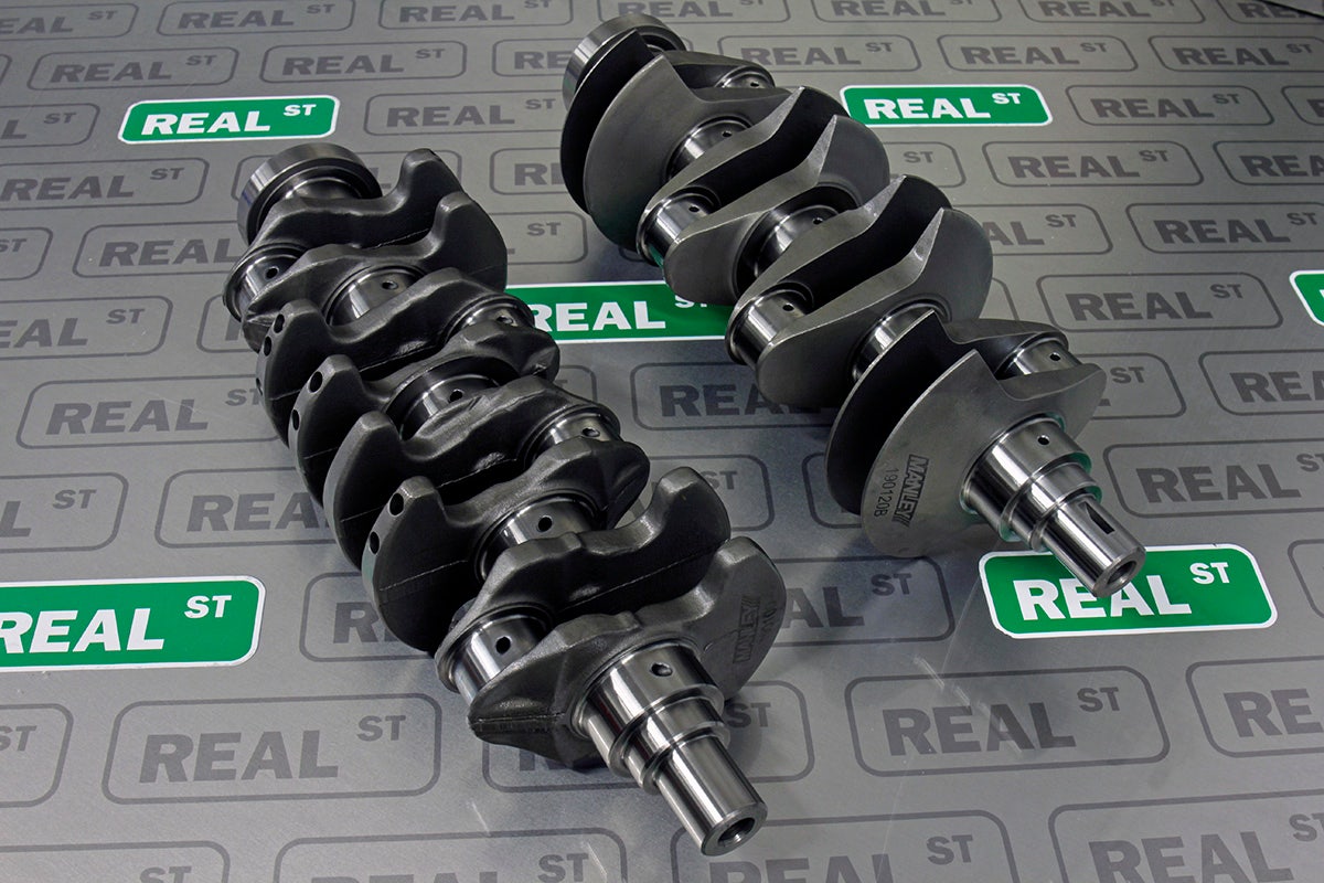
Crankshafts > Stroke
By now, you have heard about stroke in every chapter. Stroke is the distance that the piston travels from top to bottom. It is dictated by how far the rod journals are from the centerline of the crankshaft. The stroke is important because it determines the size of the engine. You can increase the size of the engine by increasing the stroke, or decrease the size of the engine by decreasing the stroke.
Bigger engines make more power and torque and are more fun to drive. They spool turbochargers faster, have more low end grunt, and more area under the power curve. But making your engine bigger with stroke can cause it to wear faster at higher rpm.
The longer the stroke, the more extreme of an angle the connecting rod will rotate through. This can put the piston into a side-loading condition that can scuff the sides of the piston against the cylinder walls and accelerate their wear.
Alternatively, de-stroking or reducing the stroke can relieve side loading on the piston making short-stroke engines easier on the piston in high rpm applications.
Crankshafts > Stroke > Summary Notes
-
Increasing the length of the stroke makes the engine bigger, more powerful, and more fun to drive, but also makes it wear faster at higher rpm. So longer stroke configurations are better for vehicles with transmissions that do not like to shift at high rpm.
-
Decreasing the length of the stroke makes the engine smaller, decreases rod angle, and decreases side loading of the piston which can allow it to live longer in higher rpm applications. So shorter stroke configurations are better for vehicles that have to perform and survive at higher rpm.
Crankshafts > Weight & Material
This is another case where the Strength vs Weight vs Price Compromise will come into play. Just like pistons or rods, crankshafts are also made stronger by using more material, which makes them heavier. Crankshafts are another one of the many engine components that can fail from being overpowered.
There are heavy duty crankshafts that are designed to live in high power max effort applications. Or for naturally aspirated racers that are trying to lighten every part of the engine as much as possible, there are lightweight crankshafts as well.
The 3 most common types of crankshafts you will find are cast, forged, and billet.
Cast crankshafts are made by heating up metal till it has melted into liquid form, then pouring it into a mold and letting it cool down. Cast cranks are the least expensive, and are often what you find in factory vehicles that were not designed to make a lot of horsepower. They are inexpensive to mass produce, but they are not very strong. This makes them a poor candidate for performance applications.
Forged crankshafts are made by heating up a big chunk of metal till it's glowing, and then smashing it into shape with crankshaft shaped dies. This method produces a stronger part than casting because it allows more control over the consistency of the material properties during production, but is more expensive to produce.
Billet crankshafts are made by putting a large cylinder of forged steel into a lathe and spinning it against a cutting tool that cuts material away until what’s left is a finished crankshaft. This method provides the most control over the material properties throughout the production process, which can produce a stronger part. But this method usually costs the most money as well.
Crankshafts > Weight & Material > Summary Notes
-
Most factory cast crankshafts are not appropriate for high performance applications, and should be swapped out for forged or billet versions.
-
Lightweight crankshafts should be reserved for naturally aspirated applications that will not see horsepower levels reached with forced induction.
Bearings > Material (Race vs Non Race)
Bearings are soft metal shells that are installed between moving parts of the rotating assembly to prevent them from the wear of contacting each other. There are bearings between the connecting rod and the crankshaft, and there are bearings between the crankshaft and the block.
Most manufacturers make at least 2 different styles of bearings. The simplified name for these styles are “Race Bearings” and “Non Race Bearings”.
Non race bearings are usually composed of 2 layers and are harder than race bearings, so they don't wear as fast. They are designed to live for hundreds of thousands of miles of daily commuting in factory engines. But they are not very good at absorbing the increased shock of combustion forces in high performance applications.
Race bearings are usually composed of 3 layers are are softer than non race bearings, so they typically wear faster. Because they are softer, they can absorb more abuse in high performance applications, but they also need to be replaced more often than a non race bearing in a factory vehicle.
Bearings > Size
Just like the cylinder walls in the piston chapter, the crank journals can also change size, shape, or surface finish over time. If this happens, the crankshaft will either need to be replaced, or machined. If the decision is made to repair the crankshaft by machining it, the surface material with the imperfections will be cut away until a better surface finish is revealed. However, this process then makes the diameter of the crank journal smaller. Making the crank journal smaller means there will now be a bigger gap between the crankshaft and the main journals of the block when you install it.
This larger gap gets made up for by using a thicker bearing.
Like pistons, you can order bearings in service sizes larger in stock. The size of the bearing will be determined by how much material was removed from the crankshaft.
“Bearing Clearance” or “Oil Clearance” refers to how tight the crankshaft fits inside the block or the connecting rods. If the fit is too tight, there won't be enough oil moving between the moving pieces, and the engine will wear prematurely or possibly even fail. If the fit is too loose, too much oil can pass between the moving parts, lowering oil pressure, and affecting the reach of the oil flow. Too loose can also cause premature wear or failure. Like piston to wall clearance, bearing clearance is a measurement you want to have control over setting, not something you randomly end up with.
If a crank is being repaired with machining, the machine shop can build the proper bearing clearance in while cutting the crank. But most cranks will not require machining.
There are 3 bearing sizes designed to help you set bearing clearance with a non machined crankshaft.
The first is a Standard Sized bearing (STD). These bearings are designed to factory dimensions. Depending on the condition of the block and crankshaft, many people can get away with using standard sized bearings. However, if you measure the bearing clearance with a standard sized bearing, and the clearance is a little too tight, most manufacturers make an extra clearance bearing.
Extra clearance bearings are usually denoted by an HX or STDX in the part number. The X usually stands for extra clearance. These bearings are 0.001” thinner than standard and loosen the oil clearance by 0.001”. If you need to loosen the bearing clearance by less than 0.001”, you can use one side of an extra clearance bearing, and one side of a standard sized bearing together on the same journal to loosen bearing clearance by 0.0005”.
If the bearing clearance with a standard sized bearing is just a little too loose, you can use a bearing that is 0.001” thicker than standard size. This will tighten the bearing clerance up by 0.001”. If you need to tighten the bearing clearance by less than 0.001”, you can use one side of a 0.001” thicker bearing, and one side of a standard sized bearing together on the same journal to tighten the bearing clearance by 0.0005”.
These 3 bearing sizes will help you fine tune the bearing clearance exactly to the ideal measurement for your application.
Studs & Fasteners > Lifespan & Reusability
There are lots of important studs and bolts that hold your engine together. But 2 of the most important ones are the Head Studs and the Main Studs. Some vehicles come from the factory with studs in these locations, while others come with bolts. The head stud’s job is to hold the head and the block together, and the main stud’s job is to hold the crank inside the block.
Some of the fasteners in your engine may be designed to only be used once. This means as you tighten them down for the first time, they stretch to a maximum limit where they can hold the most load. This can permanently change the shape of the fastener and it most likely will not work as designed if reused.
Even fasteners that are designed to be reused can change side and shape over time, after being retorqued multiple times.
The strength vs weight vs price compromise is very prevalent during fastener and stud selection at engine manufacturers. Premium studs and fasteners are more expensive than economy fasteners. So when a vehicle manufacturer decides what fasteners to put in an engine, they save expense by selecting a fastener that is appropriate for the factory power level. Choosing a more premium fastener than is needed would drive the cost of the car up unnecessarily.
So this is something we have to take into consideration when building a high performance engine. Not only should we avoid reusing used or high mileage fasteners, but we should also remember that the factory fasteners were chosen for the factory power level, and not for the high performance level we intend to run the engine at.
Head studs and main studs come in a variety of different premium materials. Some more expensive than others. Each have their own tensile strength clamping capacity.
As the engine is firing, the combustion and rotation are either pushing the parts together, or pulling them apart. Fasteners are the only thing holding the parts together while this is happening. The stronger the engine and the faster it turns, the harder it becomes to hold the parts together. This is why there are varying levels of fastener material. Your fastener selection should reflect the power level and rpm the engine will be expected to withstand.
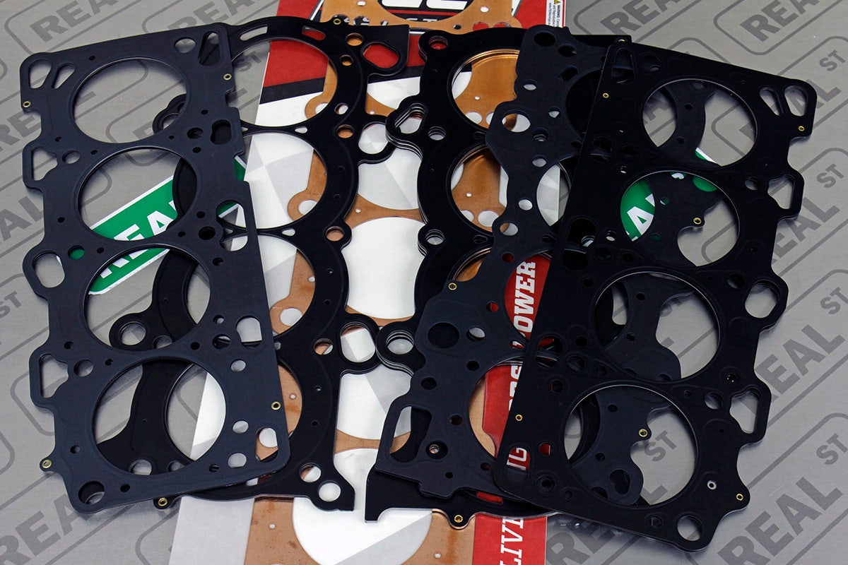
Gaskets > Bore Size
The head gasket can be found sandwiched between the head and the block of the engine. It's job is to seal combustion inside the combustion chamber, preventing it from leaking out of the crack between where the head bolts to the block. The head gasket has cylinder bore holes cut in it that line up with the cylinder holes in the block. The cylinder bore holes in the gasket are intentionally cut a little larger than the actual bore, to prevent any of the gasket from hanging over the edge into the combustion chamber. If the gasket were to hang over into the combustion chamber, it would get very hot, become damaged, and cause detonation in the engine.
It is common for the actual gasket bore to be slightly larger than it is advertised. For example, if you buy an 81mm head gasket, the actual hole will measure slightly larger than 81mm to prevent any overhang. Some people will play it even safer, and order a gasket with next bore size up from their block to make the possibility for overhang even less likely.
When selecting a gasket for your engine, you can either select the same bore size as your block, or one service size (0.5mm / 0.020”) larger.
Gaskets > Thickness
Aftermarket performance head gaskets come in a variety of sizes. There are two reasons why someone would want to run a head gasket that is thicker or thinner than stock.
Over time, the mating surface of the block and the head can change. They can develop imperfections or even warp, making them no longer flat. It is important that the mating surfaces of the block and the head are flat and smooth in order to make an aftermarket gasket seal. So it is normal for these surfaces to be machined flat and smooth again during an engine rebuild. This process removes material. When material is removed from the top of the block, or bottom of the head, the pistons get closer to the valves, and the compression ratio of the engine increases. To avoid these problems, a thicker than stock head gasket can be used to make up the difference of the material removed from machining.
Head Gasket thickness can also be used to make intentional minor adjustments to compression ratio. A thicker head gasket will decrease compression ratio, and a thinner head gasket will increase compression ratio. Major changes in compression ratio should happen with the piston however, not the gasket. Too thick of a gasket could have trouble sealing between it's layers, and too thin of a head gasket could cause engine components to colide with each other.
Gaskets > Material & Layers
Many factory gaskets are made from a soft composite material that does a great job of sealing in factory conditions, but does not hold up to the abuse of performance applications very well. These composite gaskets are also usually one time use gaskets that should not be reused during a rebuild. Most aftermarket head gaskets are made of multiple layers of steel that are riveted together. The top and bottom layer can sometimes be covered in a rubber like coating to help seal against the mating surfaces of the block and the had.
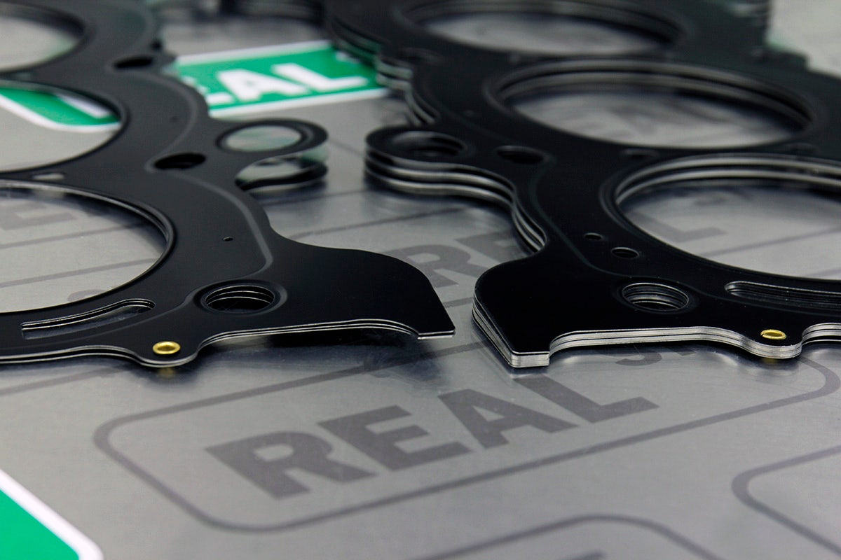
The area to pay the most attention to when it comes to layer composition however is around the edge of the bore hole. There is a lot of engineering design that goes into this section to help seal the combustion inside the combustion chamber. Some gaskets fold the outer layers over the inner layers, while others double up the middle layer around the cylinder to increase the clamping load in that specific area.
If your engine came from the factory with a multi layer steel head gasket, you may be perfectly fine going with a brand new oem gasket during your performance engine build. Engines like the Toyota 2JZ-GTE, and Mitsubishi 4G63 (evo) came from the factory with very nice multi layer steel head gaskets that hold up to a lot of power. But if your engine came from the factory with a composite head gasket, you should consider upgrading to a multi layer steel gasket for your performance engine build.
Sleeves > Material
Earlier in the piston chapter, we learned that some engines come with “exotic” materials in their engines. Engines like the Honda H22A, F20C, F22C, and several others come with fiber reinforced metal cylinder walls that do not work well with common 2618 alloy pistons.
We also learned that it is usually not very safe to bore a factory cylinder much past 1mm over standard bore because as the block material becomes thinner between the cylinders, it becomes easier to crack.
Much like many of the other parts in the engine, the block was designed to handle a certain amount of power. When we make the decision to push it past that level, we have to take block strength into consideration.
The option that many of the people in any of these cases have is to replace their factory cylinders with aftermarket sleeves. Aftermarket sleeves are made of a stronger material that has no problem working with 2618 alloy pistons, and can safely be bored larger than 1mm over standard size. The installation process is invasive, clostly, and irreversible, but the result is a very strong block with a wide selection of pistons, and the ability to run large bores that increase engine size.
Sleeves > Wet vs Dry
Some factory engine blocks route coolant passages around the outside surface of the cylinder to help cool it down by drawing heat out of the cylinder and into the coolant passing by. These blocks are often referred to as “open deck”. If the block has no passages around the cylinder, it is often referred to as “closed deck”. If your engine was open deck from the factory, you may have the option to run wet sleeves. These aftermarket sleeves are designed to retain the functionality of the factory cooling passages, and help draw heat away from the sleeves with coolant. Sleeves that do not utilize water cooling are called dry sleeves.
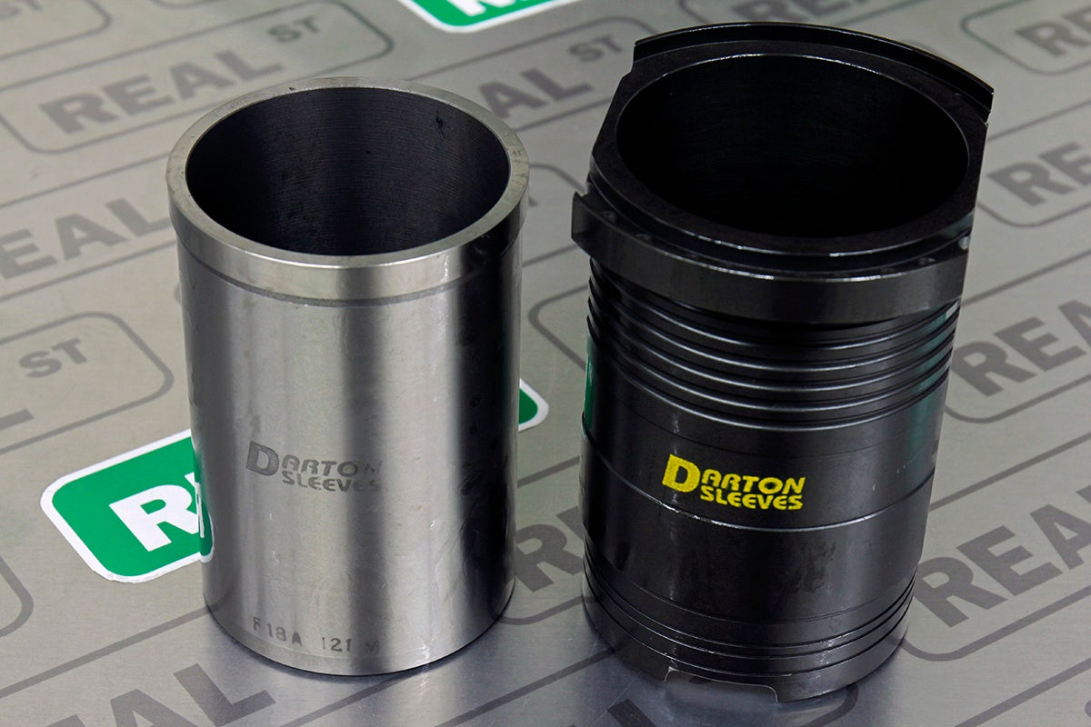
Sleeves > Flanged vs No Flange
Some sleeves are installed by boring enough of the inside of the cylinder away till an aftermarket sleeve can be inserted into it. These types of sleeves are typically used in stock rebuilds but not performance applications.
Sleeves that are designed for high power performance applications usually have flanges across the top that are designed to mate against each other as a locating support. To install these types of flanges, the entire factory cylinder structure is gutted out of the block, and the flanged sleeves become the new cylinder structure. The aligned flanges integrate into the deck of the block for added support.
If you are building an engine for high horsepower, it is recommended that you use a flanged sleeve.
Summary
As you have seen there are a lot of options to consider when selecting parts for your bottom end build. It can be overwhelming, but it's an expensive project and you should take your time learning the necessary information to make decisions confidently.
Just remember, if you get overwhelmed at any point, there are professionals waiting to help you through the process. This is what we do every day. Whether you need us to work up an entire plan from scratch, or you are just looking for a second opinion on your own plan, we are available to guide your project along to success.
 Share
Share
 Share
Share
 Email
Email
 Share
Share